The IADC dull grading system gives rig teams a consistent way to describe a used bit after it comes out of the hole. A complete record covers wear on the inner and outer cutting structures, the main dull characteristic and its location, bearing and gauge condition, another observed condition, and the reason the bit was pulled. Used consistently, those eight fields help teams compare runs, investigate failures, and make more defensible bit and operating decisions.
This field guide explains how to record the eight positions, what common PDC and roller cone damage can indicate, and how to turn a dull bit evaluation into a practical follow-up plan. Treat the grade as a structured observation—not proof of a single root cause. Confirm code definitions against the IADC dull grading chart and the chart version used by your operation.
Why Accurate IADC Dull Grading Is Essential for Drilling Optimization
A dull bit is a record of what happened during a run. It can show where wear concentrated, whether cutting elements were damaged or lost, whether a roller cone bearing system deteriorated, and whether the bit came out because it was worn or because the operation required a trip. That evidence is valuable only when the inspection is repeatable and the observations are recorded clearly.
Reliable drill bit wear analysis helps teams compare bit designs and operating practices under comparable formations and drilling conditions. It can also identify patterns that deserve investigation: repeated shoulder damage, recurring nozzle erosion, an increasing number of broken cutters, or bearing trouble on similar roller cone runs. These patterns can guide a review of formation changes, hydraulics, weight on bit (WOB), rotary speed (RPM), vibration, and drilling-fluid conditions.
The economic link is practical. A bit that wears out early may require an unplanned trip, while a bit pulled in good condition may indicate that the run ended for another operational reason. Teams can compare run cost and footage using their own cost-per-foot method, including relevant bit, trip, and rig-time costs. Do not compare unlike runs without accounting for differences in formation, hole section, operating parameters, and reason for pulling.
Good grading also improves communication between the rig, the operator, and the bit supplier or repair team. “The bit was damaged” is not enough to select a useful next action. “Several shoulder cutters chipped, with visible body erosion near the same area” is a more actionable observation—especially when supported by photographs and operating data.
The 8-Character IADC Dull Grading System Decoded (Inner, Outer, Dull Char, Location, etc.)
The conventional IADC dull grading record is written as eight fields, commonly shown as I-O-D-L-B-G-O-R. Each field has a separate purpose. The first two describe cutting-structure wear; the remaining fields record the observed damage, its location, mechanical or gauge condition, an additional characteristic, and why the bit was removed.
| Position | Field | What to record |
|---|
| 1 | Inner wear | Wear grade for the inner cutting structure or inner bit area, using the applicable 0–8 scale. |
| 2 | Outer wear | Wear grade for the outer cutting structure or outer bit area, using the applicable 0–8 scale. |
| 3 | Dull characteristic | The principal observed dull condition, recorded using the relevant IADC characteristic code. |
| 4 | Location | Where the principal condition occurred, using the chart’s location codes for that bit type. |
| 5 | Bearing/seal | Bearing and seal condition for applicable roller cone bits; use the specified not-applicable convention for fixed-cutter bits. |
| 6 | Gauge | Whether the bit is in gauge or under gauge, recorded using the applicable chart convention and measurement. |
| 7 | Other dull characteristic | A secondary observed condition not already captured by the principal dull characteristic. |
| 8 | Reason pulled | The operational reason the bit was removed from the hole, recorded with the applicable reason code. |
Grade wear and identify its location separately
For the inner and outer wear fields, the commonly used scale runs from 0 to 8, with 0 representing no visible wear and higher numbers representing increasing wear. A grade of 8 indicates extreme wear under the grading convention; it should not be treated as a precise measurement of lost cutter volume. Apply the relevant IADC chart consistently, and do not substitute a subjective percentage for its defined scale.
Location codes help show where the damage occurred. The chart may identify zones such as center, nose, taper, shoulder, or gauge, with terms and code definitions applied according to bit type and the chart in use. Inspect the whole cutting structure before assigning a location. A single damaged cutter at the shoulder should not be reported as generalized bit-wide wear.
Separate observed condition from reason pulled
The dull characteristic describes what the inspection found; the reason-pulled field describes why the crew made the trip. Those are different facts. For example, a bit can be pulled for a planned change or an operational issue while still showing limited wear. Conversely, visible damage may contribute to a decision to pull. Record the actual pull reason from the tour report or drilling records rather than inferring it from the damage.
Use the current chart approved for your operation when assigning abbreviations. Code lists and conventions can differ by bit family and chart edition. If a code is uncertain, describe the condition in words and have the responsible drilling or bit specialist confirm the code before the record is finalized.
Common PDC Bit Wear Patterns: Thermal Cracking, Impact Chipping, Ring Outs, and Delamination
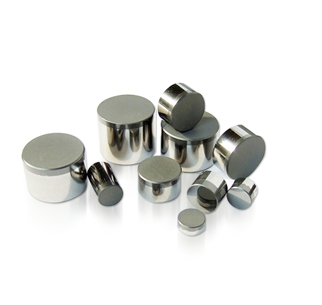
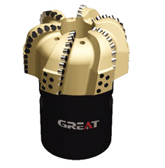
PDC bits cut by shearing formation with fixed diamond cutters. Their wear pattern depends on cutter position, rock strength and abrasiveness, bit design, hydraulics, and drilling parameters. When examining a PDC bit, record the affected zone, number and distribution of damaged cutters, evidence of body or blade erosion, and whether the damage is isolated or repeated across the bit.
| Observed pattern | What it may indicate | Field checks |
|---|
| Thermal cracking or heat checking | Repeated heating and cooling, excessive cutter temperature, or a combination of operating and formation conditions. | Review circulation, nozzle condition, flow and cuttings removal; check the affected cutters and compare with the run’s WOB, RPM, and time in operation. |
| Impact chipping or broken cutters | Impact loading, vibration, hard stringers, formation changes, or contact with junk. | Map the damaged cutters by zone; review vibration, torque, WOB, RPM, and formation transitions; check for evidence of foreign material. |
| Ring out | A cutter has fractured or separated around its perimeter; the pattern can be associated with severe impact or thermal stress. | Photograph the cutter and surrounding pocket; check whether damage is isolated or repeated and review the operating record for shocks or heat-related concerns. |
| Delamination or bond failure | Separation within the cutter structure or at a bonded interface, depending on the specific failure appearance. | Record the number, location, and appearance of affected cutters; preserve the bit for detailed inspection and supplier review if the failure is recurring. |
| Flat or worn cutting faces | Progressive abrasive or mechanical wear; the distribution may help distinguish localized from broad wear. | Compare inner and outer grades and assess formation abrasiveness, footage, and the cutter layout affected. |
| Body or blade erosion | Fluid and solids erosion that can be associated with flow paths, abrasive drilling fluid, or inadequate protection. | Note erosion location and severity; inspect nozzles and fluid passages and review circulation and solids-management records. |
Do not diagnose thermal cracking from appearance alone. Heat checking, impact damage, and manufacturing or material-related failure can produce overlapping signs. A PDC cutter wear grading record should include clear photographs and a description of the visible condition. Repeated damage in the same zone across runs is more useful diagnostically than a single code without context.
Bit design matters when comparing observations. Cutter size, layout, blade configuration, gauge protection, and hydraulic design influence how loads and fluid act on the cutting structure. For bit-specific design details, see GREAT’s PDC drill bit information. Match any design discussion to the actual bit model and operating application rather than assuming all PDC bits respond the same way.
Common Roller Cone Wear Patterns: Broken Teeth, Bearing Play, Seal Loss, and Skidded Cones
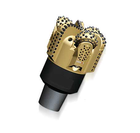
Roller cone bits break rock as the cones rotate and their teeth or tungsten carbide inserts crush, indent, or scrape the formation. Dull evaluation must cover the cutting elements as well as the cone, bearing, seal, and gauge condition. A cone that no longer rotates freely can change how the bit contacts the bottom and may create further damage.
Broken or chipped teeth/inserts: Record whether damage is concentrated in one cone or occurs across several cones. Impact, formation changes, wear, or operational shocks may be relevant; the pattern alone does not prove which one occurred.
Bearing play or failure: Note visible looseness, restricted rotation, or a cone that does not turn normally during safe inspection. The bearing/seal grade is a structured condition rating, not a substitute for a teardown or specialist inspection.
Seal loss or leakage evidence: Record visible signs and any associated bearing or cone condition. Review run history and bit type because internal seal condition may not be fully assessable at the rig site.
Skidded or non-rotating cone: Look for uneven tooth or insert wear consistent with a cone that did not rotate as intended. Check for cone damage and bearing problems, then correlate the finding with operating records.
Gauge wear or under-gauge condition: Measure the bit using the site’s approved method and record the result. Do not estimate under-gauge condition from photographs alone.
For tricone bearing failure diagnosis, record what can be observed without overstating what can be confirmed in the field. Bearing condition may be partly hidden inside the cone assembly. The dull code, photographs, cone rotation observations, and any repair or teardown findings should remain linked so the final diagnosis is evidence-based.
Tracing Root Causes: Was It Formation, Hydraulic Inadequacy, or Parameter Mismanagement?
A dull grade identifies a condition; root-cause analysis tests explanations against the drilling record. Avoid assigning every broken cutter to excessive WOB or every eroded area to poor hydraulics. Compare the damage pattern with formation information, time and depth intervals, operating parameters, and bit design.
| Possible contributor | Evidence to review | Useful follow-up |
|---|
| Formation change or hard stringers | Geological or offset information, changes in ROP and torque, and the depth interval where damage may have developed. | Compare the interval with the dull location and damage pattern; reassess bit type and cutting structure for the next run. |
| Hydraulic limitation or erosion | Flow and pressure records, nozzle configuration and condition, mud properties, cuttings transport, and visible erosion locations. | Check for plugged or damaged nozzles and review whether fluid delivery and cleaning were appropriate for the operation. |
| WOB, RPM, or vibration conditions | Recorded WOB and RPM, torque behavior, shock or vibration data if available, and relevant changes during the run. | Compare operating changes with the likely depth of damage; adjust parameters only after considering tool limits and formation response. |
| Junk or contact damage | Evidence of foreign material, localized impact damage, lost components, and hole or BHA events. | Check event reports and inspect the bit and recovered material; document uncertainty when no direct evidence exists. |
| Bit selection or application mismatch | Bit type and design, formation strength and abrasiveness, hole section, and the distribution of wear. | Review the application with the bit supplier or engineering team; compare only runs with sufficiently similar conditions. |
Use a sequence: describe the damage, locate it, establish when it likely developed, compare plausible causes, then define a testable action. For example, a repeated shoulder-damage pattern may justify reviewing vibration and formation transitions as well as cutter layout. It does not, by itself, prove a particular WOB or RPM setting was wrong.
Parameter changes should be made by the responsible drilling team within the operating limits of the bit, BHA, motor, and rig. A dull report is one input to that decision, alongside real-time drilling data and well objectives.
Standard Field Dull Bit Grading Sheet and Action Plan Template
Use the following worksheet at the rig or inspection area. Record observations before cleaning or handling could remove evidence. Photograph the bit from the face, side, and close range, and include a scale or clear reference where practical. Follow site procedures for lifting, handling, and inspection.
| Inspection item | Field entry |
|---|
| Well / hole section / bit serial or identifier | ________________________________________ |
| Bit type, size, and design | ________________________________________ |
| Run start and end depth; footage drilled | ________________________________________ |
| Formation summary and notable changes | ________________________________________ |
| Recorded WOB, RPM, torque, flow, and pressure observations | ________________________________________ |
| IADC fields: I – O – D – L – B – G – O – R | ________________________________________ |
| Observed damage by bit zone; number of affected cutters, teeth, cones, or nozzles | ________________________________________ |
| Gauge measurement and method | ________________________________________ |
| Reason pulled, confirmed from the operational record | ________________________________________ |
| Photos, inspection notes, and unresolved questions | ________________________________________ |
| Likely contributing factors and evidence supporting each | ________________________________________ |
| Action for next run; owner and review date | ________________________________________ |
Turn the inspection into a controlled action
Complete the eight-field grade using the chart approved for the bit type and operation.
Write a plain-language description of the main and secondary damage. Do not rely on codes alone.
Attach photographs and the relevant run data, including parameter changes and reported hole events.
Separate confirmed observations from suspected causes. Note what additional evidence is needed.
Assign a specific review action, such as checking nozzle condition, comparing similar runs, or requesting a bit inspection.
After the next run, compare the result under the new conditions and record whether the action addressed the observed pattern.
Consistent dull bit evaluation makes bit selection and operating reviews more useful over time. If your team is investigating recurring cutter or roller cone damage, share the bit details, formation information, drilling parameters, photographs, and pull reason with a qualified drilling-tool specialist. GREAT manufactures drilling tools for multiple applications; a project-specific recommendation should be based on the operating conditions and confirmed bit requirements, not on a dull code alone.
 English
 français
 Deutsch
 Español
 italiano
 русский
 português
 العربية
 tiếng việt
 ไทย
 Nederland