Successful downhole motor drilling depends on matching the motor’s power section, bend assembly, and operating limits to the bit and the well plan. A motor’s lobe configuration influences its speed and torque characteristics, while the bent housing and BHA determine how the assembly builds angle. The bit must then operate within the motor’s available torque, speed, flow, and hydraulic envelope.
This guide explains how those components work together. It is intended for directional drillers, BHA design engineers, rig superintendents, and tool-rental teams planning a positive displacement motor (PDM) assembly. Exact motor limits vary by model and service condition, so use the tool-specific operating manual and supplier data for final settings.
How Does a Positive Displacement Downhole Motor (PDM) Work?
A positive displacement downhole motor converts drilling-fluid flow into rotation at the bit. Drilling fluid passes through the motor’s power section, where a helical rotor turns inside a matching elastomer-lined stator. The rotor and stator form sealed cavities. As fluid moves through those cavities, pressure and flow drive the rotor around its eccentric path.
The rotor’s motion is not initially the same as the concentric rotation required by the bit. A transmission section, commonly using universal-joint assemblies or another model-specific coupling arrangement, transfers the rotor’s eccentric motion as rotary torque to the output shaft. The bearing assembly supports radial and axial loads and carries the rotation to the bit connection. The exact design depends on the motor.
In practical terms, flow rate is a key influence on motor speed, while the pressure differential across the power section is a key indicator of delivered load and torque. These are related but not interchangeable: increasing flow is not a substitute for providing the right torque, and pressure readings must be interpreted against the motor’s published limits and the rest of the circulating system.
The complete assembly also includes connections, housing sections, and a bit interface selected for the drill string and operating conditions. A motor that fits the nominal hole size is not automatically compatible with a planned BHA. Confirm connection dimensions, motor and bit clearances, flow requirements, pressure limits, and the directional objective together.
For product and configuration discussions, see GREAT’s downhole motor. A project-specific selection still requires the planned hole section, drilling fluid, operating limits, and bit details.
Rotor and Stator Lobe Configurations: High Torque vs High Speed Power Sections
The rotor and stator lobe count is a useful first comparison when selecting a mud motor power section. A lobe configuration is written as rotor lobes:stator lobes. Different configurations create different cavity geometry and displacement characteristics. In general, lower rotor-to-stator lobe-count configurations tend toward higher speed and lower torque, while higher-lobe configurations tend toward lower speed and higher torque at comparable design conditions.
That general relationship is a selection guide, not a performance guarantee. Lobe count alone does not determine output. The motor’s number of stages, rotor and stator geometry, elastomer, displacement, condition, fluid properties, and pressure differential all affect the torque-speed response. Compare the manufacturer’s curves and operating envelope for the specific motor rather than selecting by lobe ratio alone.
Use the full motor torque curve to assess the expected operating point. Check the motor’s recommended flow range, differential-pressure limit, maximum operating pressure, speed response, and connection details. A higher-torque section may suit a bit and formation that demand sustained loading, but it is not automatically the best choice if the planned bit runs efficiently at a different speed or if the rig’s hydraulic system cannot support the required operating window.
Transmission and bearing sections matter as much as the power section in a working BHA. They carry output torque and drilling loads, and their ratings must be compatible with the intended motor and bit operation. Confirm that the motor’s output connection, transmission design, bearing capacity, and bit connection are specified for the planned service. Do not infer a motor’s complete load capacity from lobe count.
Adjustable Bent Housing: Setting Dogleg Severity (DLS) in Curve Sections
A downhole motor bent housing offsets the bit’s rotational axis from the drill-string axis. With the drill string held against rotation, the bit follows the direction established by the housing bend and BHA contact points. This is sliding mode: the motor turns the bit, but the drill string is not continuously rotated from surface. When the string is rotated, the assembly tends to drill a more rotationally averaged path, subject to BHA design and borehole conditions.
Adjustable-bend designs allow the bend setting to be configured within the motor manufacturer’s approved range. The bend angle is not the dogleg severity. DLS is the change in wellbore direction over a measured length, and the result depends on the full BHA, hole size, stabilizer placement, motor dimensions, formation response, drilling parameters, and operating mode. Therefore, do not convert a bend angle directly into a predicted DLS without an engineering model and field validation.
For a curve section, select the bend setting to meet the trajectory plan while keeping the motor, bit, and BHA within their mechanical and drilling limits. A more aggressive steering setup may increase the assembly’s tendency to build or turn, but it can also affect toolface control, contact forces, wear, and the ability to maintain a smooth hole. The suitable setting depends on the target trajectory and actual formation behavior.
Before running, confirm the required bend setting, how it is measured and locked, the motor’s toolface orientation procedure, stabilizer and near-bit assembly dimensions, and the planned method for switching between sliding and rotating. Align the steering plan with survey intervals and the directional driller’s method for tracking toolface response. If the motor is rented, document the as-received setting and verify it before making up the BHA.
Matching Downhole Motors with PDC Bits vs Tricone Bits
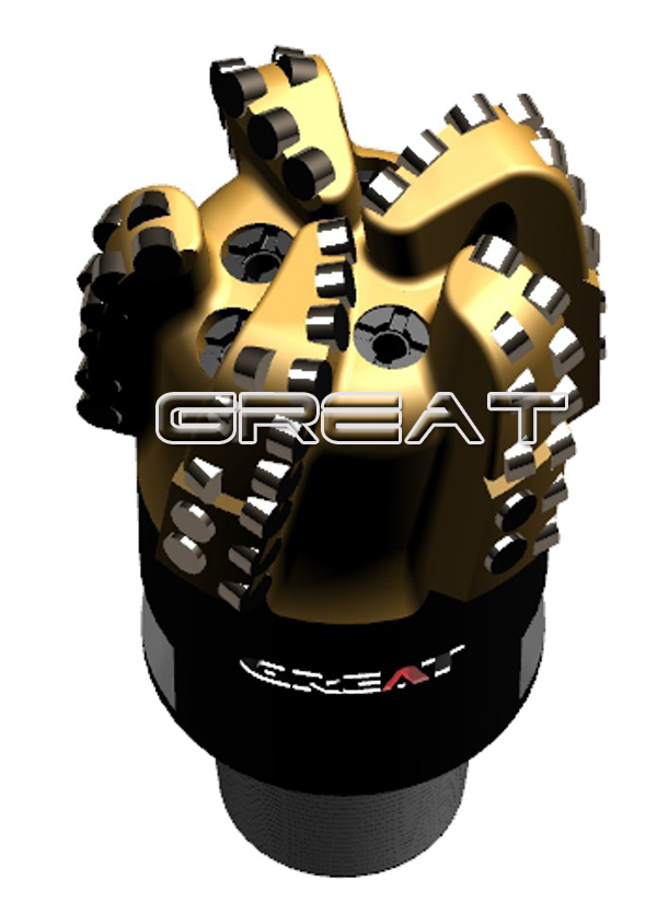
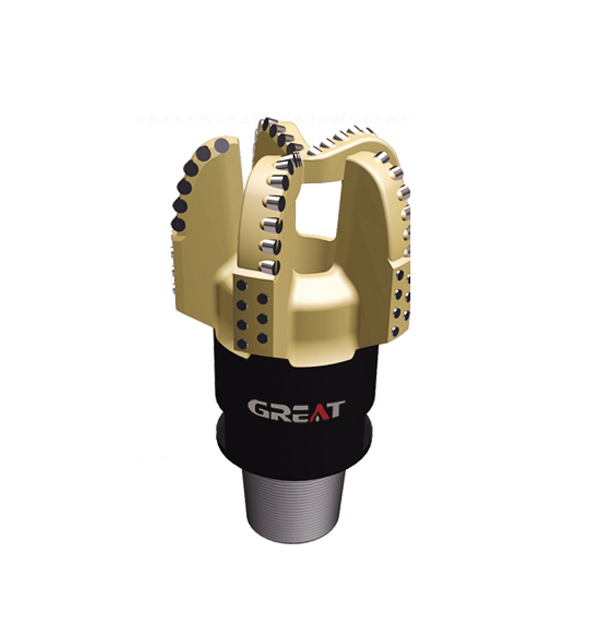
Mud motor bit pairing begins with the bit’s torque and speed requirements, not simply its nominal diameter. Match the bit’s operating envelope to the motor’s output curve, then check the formation, hydraulic requirements, drilling fluid, and BHA. The bit must also have the correct connection and clearance for the motor assembly.
A PDC bit paired with a motor needs a stable operating point. Check whether the planned motor speed and expected torque suit the bit’s cutter design and the formation’s strength and abrasiveness. If the bit encounters variable or fractured rock, consider the possibility of torque fluctuation and vibration. Bit selection, motor choice, and operating practices should be reviewed together rather than treating the motor as an independent power source.
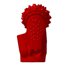
A tricone bit may be considered where its rolling-cone cutting action and formation-specific structure fit the application. Its interaction with a motor differs from surface rotary drilling because motor output speed and torque are delivered downhole. Confirm that the selected cone design, bearing system, and bit operating window can tolerate the expected motor conditions. Avoid assuming a tricone is inherently more tolerant of motor stalls or unstable operation.
For either bit type, check the complete hydraulic path. Motor flow contributes to power-section operation, while bit nozzles direct fluid for cleaning and cuttings transport. The selected nozzle configuration and circulating system must support the motor’s required flow and maintain suitable cleaning without exceeding pressure constraints. Include the drill string, annular path, and other BHA components in the hydraulic review.
Managing Differential Pressure, Stalling, and Mud Flow Rates Downhole
Differential pressure is the pressure drop across the motor power section while it is working. It rises as the motor takes load, within the limits defined for that motor. The surface pressure reading includes other losses in the circulating system, so it should not be treated as a direct measurement of power-section differential pressure unless the pressure references and operating method support that interpretation.
A stall occurs when the bit and motor load exceed the motor’s ability to continue rotating under the current operating conditions. A stall can produce a sharp change in pressure and interrupt drilling. Repeated stalls can place avoidable stress on the power section, transmission, bearings, connections, and bit. Follow the motor supplier’s stall response and restart procedure; do not use a single pressure number as a universal stall threshold.
When pressure rises or the motor stops turning, assess the complete system before adding load. Review flow, surface pressure, WOB, rotary conditions, cuttings transport, hole cleaning, bit condition, and possible restrictions. Distinguish a motor stall from other causes of elevated pressure or reduced returns. If the cause is unclear, use the approved troubleshooting procedure and protect the motor from repeated overload.
Flow rate influences motor speed, but the correct value is model-specific. Stay within the motor’s stated operating range and account for drilling-fluid density, viscosity, solids, temperature, and elastomer compatibility. Fluid condition can affect power-section performance and serviceability. Also verify that the rig pump and BHA hydraulics can deliver the required flow while maintaining the pressure margin needed for the rest of the system.
During operation, interpret pressure and flow together with drilling response. A change in rate of penetration, torque behavior, vibration, returns, or toolface response may indicate that the motor-bit-formation system is no longer at its intended operating point. Adjust parameters within approved limits and use downhole or surface measurements available to the crew; do not compensate for poor bit matching by exceeding the motor’s rated envelope.
Downhole Motor Procurement and Performance Verification Checklist
Before ordering or mobilizing a motor, provide the supplier and BHA designer with enough information to confirm compatibility. A motor described only by nominal size or lobe ratio is not sufficiently specified for a directional assembly.
Well and hole section: planned hole diameter, trajectory section, formation description, expected abrasiveness or interbedding, and directional objectives.
Motor configuration: motor model and size, rotor:stator lobe configuration, stage count, power-section data, bend-housing type and setting, overall length, and connection specifications.
Performance envelope: published flow range, speed response, torque curve, differential-pressure limits, maximum operating pressure, and applicable service restrictions.
Mechanical interfaces: top and bit connections, transmission and bearing specifications, BHA dimensions, stabilizer arrangement, and clearance through the planned hole.
Bit pairing: PDC or tricone type, diameter, formation suitability, recommended operating window, torque behavior, hydraulic requirements, and compatibility with motor output.
Fluid and hydraulics: mud type and properties, expected temperature and solids conditions, pump capacity, pressure losses, nozzle design, and circulation requirements.
Directional plan: intended bend setting, toolface procedure, planned sliding and rotating intervals, survey method, and criteria for reviewing actual DLS.
Inspection and documentation: confirm the delivered configuration, connection condition, power-section and bearing inspection status, operating manual, handling requirements, and service records available for the specific tool.
Commissioning agreement: document startup procedure, operating limits, pressure and flow monitoring, response to stalls, and communication between the rig crew, directional driller, and tool provider.
At the rig, verify the motor’s configuration and bend setting before makeup, check that connections and handling procedures are correct, and confirm that the bit and BHA match the approved program. Establish baseline circulation and pressure observations using the motor provider’s procedure. During drilling, record the parameters needed to compare actual behavior with the planned operating window, including flow, pressure, WOB, rotary conditions, toolface response, and drilling performance.
GREAT manufactures downhole motors alongside PDC bits, tricone bits, and other drilling tools. For a project-specific motor or bit pairing discussion, share the hole section, formation, drilling fluid, BHA, and planned operating conditions so the configuration can be reviewed as a system.
 English
 français
 Deutsch
 Español
 italiano
 русский
 português
 العربية
 tiếng việt
 ไทย
 Nederland