Directional PDC bit selection is a balance between steerability, stability, and drilling efficiency. Gauge length and pad geometry influence how the bit responds to steering commands, but they do not determine build rate by themselves. Formation behavior, bottom-hole assembly (BHA), motor or rotary steerable system (RSS), operating parameters, and wellbore condition all contribute. This field guide explains how to evaluate those interactions when planning a directional well profile.
For a practical decision, start with the steering system and the formation interval, then match bit aggressiveness and gauge behavior to the required trajectory. Confirm the final design with the bit and BHA suppliers using the planned hole size, connection, motor or RSS configuration, formation description, and operating limits.
Why Steerability and Stability Are Crucial in Directional PDC Bits
A directional bit must respond predictably when the driller steers, while remaining stable enough to drill efficiently when the assembly is rotated. In sliding mode with a bent-housing positive displacement motor (PDM), the toolface is oriented to direct the bit. In rotary mode, the assembly turns and typically drills a straighter path, subject to the BHA, formation, and steering system. A bit that is too aggressive or unstable can make toolface control harder; one that is too passive may not deliver the desired steering response.
Steerability describes how readily the bit and BHA respond to steering input. Stability describes the bit’s ability to maintain smooth contact and limit unwanted lateral motion, vibration, and torque fluctuation. These qualities are related but not interchangeable. A highly steerable bit is not automatically the best choice if it creates erratic toolface response or poor rotary behavior in the planned interval.
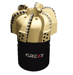
Formation changes complicate the balance. Soft and interbedded intervals may produce changes in side-cutting response, while hard, abrasive, or fractured rock can increase vibration, uneven cutter loading, and wear risk. A directional PDC bit therefore needs an appropriate cutting structure and hydraulic design as well as a gauge profile suited to the BHA. PDC cutters remove rock primarily by shearing; their response depends on cutter exposure, layout, formation, and applied load.
When comparing a PDC bit design, discuss the intended steering mode, target curve or lateral behavior, expected formation variability, and the required hole diameter. Do not select on blade count or cutter size alone. The full bit design must work with the steering assembly and drilling program.
Gauge Length and Gauge Pad Geometry: Short vs Long Gauge Profiles
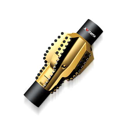
The gauge is the bit section that helps maintain the drilled hole diameter and supports contact with the borehole wall. Gauge length, pad shape, and the placement of gauge cutters affect how the bit interacts with the formation during steering and rotation. Their influence is indirect: the bit works as part of a BHA, and the resulting trajectory also depends on formation response, stabilizer placement, motor bend or RSS design, and operating practice.
Shorter gauge profiles can favor steering response
A shorter gauge contact profile may reduce the length of wall contact at the bit and can support a more responsive steering behavior in some motor-driven applications. This can be useful where the directional plan calls for active correction or where the assembly needs to initiate a curve. However, short gauge does not guarantee a higher build rate. The motor bend, bit side-cutting capability, BHA stiffness, formation, and steering procedure remain decisive.
Greater steering response can come with trade-offs. Depending on the design and conditions, the bit may be more sensitive to toolface changes or lateral loading. The team should check whether the expected interval demands frequent steering corrections and whether the selected bit can maintain acceptable hole quality and gauge condition.
Longer gauge profiles can support directional stability
A longer gauge contact profile can provide more wall support and may help the bit track steadily, especially when rotary drilling through a lateral or a section where reducing unwanted deviation is important. It may also resist abrupt lateral movement. The trade-off is that a more stabilizing profile can be less responsive to steering input in some BHA and formation combinations.
Do not treat “short gauge builds” and “long gauge holds” as universal rules. These are design tendencies, not guaranteed outcomes. A bit that appears suitable by gauge length may behave differently with a different motor bend, stabilizer arrangement, formation dip, or rock strength. Ask the manufacturer to evaluate the gauge geometry in the context of the entire BHA and the planned mode of operation.
Evaluate side-cutting and gauge protection together
Side-cutting capability is the bit’s ability to remove formation laterally as the steering system directs the assembly. It is influenced by cutter placement and exposure around the shoulder and gauge, as well as the formation and steering load. Strong side-cutting response can help a steerable PDC bit follow commanded changes, but excessive aggressiveness may contribute to torque variation or less smooth tracking under some conditions.
Gauge protection helps preserve the intended hole size as the bit wears. Ask how gauge cutters or wear elements are arranged and how the design balances lateral cutting with durability. For abrasive or variable formations, gauge wear can change bit behavior during a run, so the planned replacement criteria should consider both diameter condition and steering performance.
Mitigating Left/Right Bit Walk Tendency and Toolface Fluctuations
Bit walk is an unplanned tendency for the wellbore to drift laterally from the intended direction. It can appear as a persistent left- or right-hand trend, or as inconsistent directional response. The bit is only one contributor. Formation anisotropy, bedding orientation, BHA configuration, motor behavior, hole condition, and operating practices can all affect the observed walk tendency.
Toolface fluctuations can make that behavior harder to manage. Reactive torque from the bit and motor can rotate the BHA, changing the oriented toolface while sliding. The driller may then need to correct toolface repeatedly, which can reduce effective steering time and make the trajectory response less consistent. High or unstable torque may also indicate that operating load, formation, bit aggressiveness, or hole condition needs review.
Separate toolface change from formation-driven walk
Use MWD surveys and drilling records to distinguish a toolface-control problem from a persistent formation-related trend. Compare planned and observed inclination and azimuth changes with toolface, sliding intervals, torque behavior, WOB, motor differential pressure, and formation transitions. A consistent offset between commanded toolface and achieved trajectory may point to repeatable system or formation behavior; erratic toolface readings may instead indicate changing torque or unstable operating conditions. Confirm interpretation with the directional drilling team and available downhole measurements.
Use controlled adjustments rather than changing several variables at once
When walk or toolface instability appears, make changes systematically. Check for changes in formation, toolface holding, motor differential pressure, torque, and drilling response before changing the bit design or steering practice. Where safe and consistent with the drilling program, adjust one controllable factor at a time and observe the survey and drilling response. This makes it easier to identify the cause rather than masking it with multiple simultaneous changes.
Do not assume that increasing WOB will overcome poor steering response. Additional load can increase torque or motor load and may worsen toolface control, depending on the bit, motor, and formation. Follow the motor and bit operating limits, and coordinate parameter changes with the drilling supervisor and directional driller.
Pairing PDC Bits with Bent-Housing Downhole Motors and RSS Assemblies
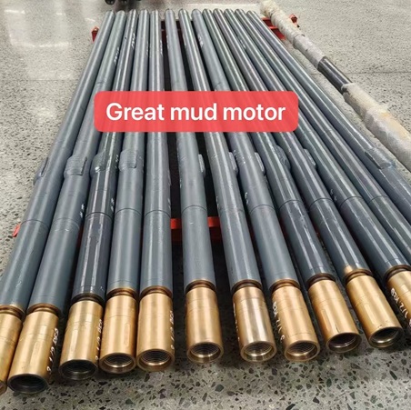
A motor-steerable bit must match the steering mechanism. With a bent-housing PDM, the assembly can be oriented and slid to steer; rotating the drill string changes the operating mode. The bit’s side-cutting response, gauge behavior, and torque characteristics influence how the motor assembly responds, but the motor bend and BHA geometry are central to the available steering capability.
For motor pairing, confirm bit-to-motor connection compatibility, hole size, motor output and operating envelope, expected bit torque, flow requirements, and the planned steering mode. The bit must fit the motor’s mechanical and hydraulic limits. Avoid specifying a highly aggressive cutter layout without considering motor torque and toolface control in the target formation.
An RSS steers while the drill string rotates, using a system-specific mechanism. “Push the bit” systems apply force through pads against the borehole wall, while “point the bit” systems change the direction in which the bit is oriented. These are broad operating principles; actual steering response and bit compatibility depend on the RSS design. A bit selected for a bent-housing motor should not automatically be assumed suitable for every RSS configuration.
For either system, share the planned directional well profile, anticipated formations, target inclination and azimuth behavior, hole diameter, drilling fluid and flow plan, and expected operating mode with the bit supplier. The objective is a compatible combination—not a bit specification considered in isolation.
Weight on Bit (WOB) and Differential Pressure Management in Curve vs Lateral Sections
WOB and motor differential pressure affect drilling response, but they are not interchangeable controls. WOB is the axial load applied at the bit. For a PDM, differential pressure is the pressure difference across the motor that develops torque and relates to motor loading. Operating limits vary by motor, bit, drilling fluid, and downhole conditions; use the equipment supplier’s specifications and the approved drilling program rather than a generic target.
Curve sections require measured steering response
In a curve, the priority is to achieve the required inclination and azimuth changes while keeping toolface control and hole quality manageable. Apply WOB and motor load progressively, then evaluate whether the assembly responds as planned. Increasing load without checking torque, differential pressure, vibration, and survey response can make steering less predictable. Follow the motor’s operating envelope and use the directional driller’s measurement-based adjustments.
Lateral sections prioritize smooth, stable drilling
In a lateral, the goal often shifts toward maintaining the planned trajectory while drilling efficiently. Rotary drilling may be favored where the assembly and plan allow it, but formation changes and BHA tendencies can still cause deviation. Monitor torque, vibration, ROP, motor differential pressure, and survey results. If the bit begins to walk or the motor loads erratically, investigate formation and operating changes before simply increasing WOB.
Maintain adequate circulation and confirm that the hydraulic design supports effective cleaning at the bit. Poor cleaning can affect drilling efficiency and may contribute to unstable operation, while excessive or inappropriate parameter changes can exceed equipment limits. The right operating window is specific to the bit, motor or RSS, fluid system, formation, and rig capability.
Directional Drilling PDC Bit Selection and Run Planning Guide
A reliable selection process connects the well plan to the bit and steering assembly. Before requesting a quote or approving a design, prepare the following information. Complete data helps the manufacturer assess gauge profile, cutter layout, hydraulic requirements, and compatibility without relying on assumptions.
Well and hole details: hole diameter, section length, planned directional well profile, curve and lateral objectives, and relevant casing or connection constraints.
Formation description: expected rock types, strength or relative drillability where known, abrasiveness, fractured intervals, bedding, and likely formation transitions.
Steering assembly: bent-housing PDM or RSS type, motor or system specifications, BHA layout, stabilizer arrangement, and intended sliding or rotary intervals.
Operating plan: anticipated WOB, rotary speed, flow range, motor differential-pressure limits, drilling fluid information, and rig restrictions.
Performance priorities: steering responsiveness, directional stability, gauge retention, vibration management, ROP, and the cost-per-foot objective.
Run and inspection plan: monitoring responsibilities, survey frequency under the well program, criteria for reviewing performance, and post-run inspection of cutters and gauge.
During the run, compare actual performance with the planned operating envelope. Track ROP together with torque, WOB, rotary speed, motor differential pressure, toolface behavior, surveys, and changes in formation. A single performance indicator rarely explains the cause of poor directional response. At the end of the run, record cutter damage, gauge condition, erosion, and any unusual wear alongside the drilling history. Those observations help refine the next bit and BHA selection.
GREAT manufactures PDC bits and other drilling tools, with product design and engineering capabilities described in the supplied company information. For a project-specific recommendation, provide the well profile, formation information, hole size, and steering assembly details so the bit design can be considered against the complete operating context. The goal is a steerable PDC bit that responds predictably without sacrificing the stability and durability required for the section.
 English
 français
 Deutsch
 Español
 italiano
 русский
 português
 العربية
 tiếng việt
 ไทย
 Nederland