Key takeaway: Deep-well bit selection is a section-by-section engineering decision, not a search for one bit that works everywhere. Formation strength and abrasiveness, downhole temperature, differential pressure, mud rheology, hydraulics, trajectory, and the rig’s operating envelope all affect the choice. For HPHT exploration and extended-reach drilling, coordinate bit design with the well plan and hydraulics model, then verify performance using field data.
This guide is for petroleum asset managers, deepwater drilling engineers, and drilling optimization teams evaluating oil and gas drill bits for demanding well profiles. It covers the practical interaction between thermal and mechanical loading, high-mud-weight hydraulics, section-specific bit programs, and gauge wear. Actual operating limits and bit specifications must be confirmed for the project, the selected product, and the drilling system.
Why Deep Exploration Wells Push Drill Bits to Their Physical Limits
A deep exploration well can combine hard or abrasive rock, high formation pressure, elevated temperature, long drilled intervals, and demanding directional requirements. These conditions load the bit and the complete drilling system at the same time. A bit that drills efficiently in a short vertical interval may not be the right choice for a long, deviated section where torque, vibration, and gauge wear can dominate.
Depth alone does not determine the correct bit. The selection depends on the sequence of formations and their mechanical behavior: compressive strength, abrasiveness, natural fractures, interbeds, and the likelihood of sticky or reactive shale. A hard, abrasive interval may wear cutters or inserts quickly. Interbedded formations can produce uneven loading and vibration. Reactive or adhesive formations can pack around the cutting structure if cuttings removal is inadequate.
High-pressure, high-temperature (HPHT) conditions add operating constraints. Pressure management can require dense drilling fluid, while elevated temperature affects the downhole environment and can challenge materials and components. The resulting mud system, circulation program, and trajectory influence bit cleaning and mechanical loading. HPHT classifications and design limits are not universal; use the definitions, equipment ratings, and operating envelope adopted for the specific project and jurisdiction.
For this reason, a deep well drilling bit should be selected against a defined interval and operating plan. Review offset-well records, formation evaluations, expected drilling parameters, and failure history where available. Distinguish dull-related wear from damage caused by vibration, poor cleaning, impact, or operation outside the bit’s recommended limits. That diagnosis is more useful than choosing a bit solely by its product category.
HPHT Downhole Dynamics: Managing Thermal Expansion, High Torque, and High Differential Pressure
At elevated downhole temperature, components expand and materials experience additional thermal stress. The effect on a particular bit depends on its construction, materials, operating conditions, and exposure time. For PDC bits, cutter stability and the integrity of the cutter-to-blade attachment matter alongside the diamond cutting surface. For roller-cone bits, bearing and seal systems must be appropriate for the specified service conditions. Confirm temperature and pressure limits with the bit manufacturer rather than assuming all designs in a category have the same rating.
Temperature also changes the drilling environment. Fluid properties can differ from surface measurements, and the actual downhole condition influences hydraulics and cuttings transport. Treat surface mud data as an input to the well model, not a complete description of conditions at the bit. Use the operator’s validated thermal and hydraulics models to assess circulation, equivalent circulating density (ECD), and available pressure margins.
Control torque and vibration through compatible bit design and operating practice
High torque can arise from formation strength, friction, trajectory, poor hole cleaning, or a combination of factors. Bit design affects how the cutting structure engages the formation, but the response also depends on weight on bit (WOB), rotary speed, bottomhole assembly, and formation changes. Excessive or unstable loading can contribute to stick-slip, impact damage, cutter chipping, or uneven wear.
Use formation-appropriate cutter layout and blade configuration for a PDC design, or an appropriate insert or tooth structure and bearing configuration for a roller-cone design. Then establish operating parameters within the manufacturer’s recommendations and the drilling program. Monitor torque, RPM, WOB, rate of penetration (ROP), vibration indicators, and drilling response together. A sudden ROP change is not, by itself, proof that the bit is unsuitable; it may indicate a formation change, cleaning problem, or operating instability.
Account for differential pressure and pressure loss
Differential pressure across the bit is related to the pressure drop through its nozzles and the flow path. It contributes to the hydraulic energy available for cleaning, but higher pressure drop is not automatically better. Excessive pressure loss can consume pump capacity, while insufficient flow or poorly directed jets can leave cuttings at the cutting structure. The appropriate balance depends on pump limits, nozzle configuration, mud properties, hole geometry, and the circulation plan.
Before running a bit, confirm pressure ratings and compatibility for the complete assembly, including the connection and relevant downhole equipment. Review the modeled operating envelope with the drilling and hydraulics teams. Do not infer a pressure rating from bit type or nominal diameter alone.
High Mud Weight Hydraulics: Preventing Bit Balling and Optimizing Jet Impact Force
High mud weight is used as part of well-pressure management, but a dense fluid system can make hydraulic optimization more demanding. Mud density is only one input. Rheology, solids content, temperature-dependent behavior, flow rate, nozzle total flow area (TFA), drillstring geometry, and annular clearances all influence circulating pressure losses and cuttings transport. The practical aim is to clean the bit and hole effectively without exceeding the pressure and ECD limits of the well plan.
Bit balling occurs when sticky cuttings or formation material accumulate on the bit and reduce effective cutting action or flow. It is more likely when the formation and fluid behavior promote adhesion and when cleaning is inadequate. It is not solved by changing nozzle size alone. Review the formation, mud formulation and condition, flow path, and operating parameters together. If balling is suspected, check for supporting evidence such as declining ROP, changing torque, or poor cuttings condition, and follow the well’s approved response procedures.
Optimize nozzle configuration with a hydraulics model
Nozzle size and TFA influence the bit pressure drop and the flow delivered through the bit. Jet velocity and impact at the bottom of the hole depend on flow rate, nozzle area, fluid properties, and the nozzle arrangement. Therefore, do not select nozzles using mud weight alone or assume that the smallest available nozzle produces the best cleaning. Model candidate configurations against pump capacity, expected fluid properties, pressure losses across the full circulation system, and the planned operating range.
Check whether the model’s assumptions represent the mud system at operating conditions. Include likely changes in rheology and solids loading where the available data support them. Confirm that the proposed bit configuration leaves adequate hydraulic margin for the actual program. If the well has narrow pressure margins, review ECD and pump limits with the drilling team before finalizing the bit and nozzle specification.
In abrasive or solids-rich service, nozzle and flow-path erosion can also change the intended hydraulic performance over time. Inspect returned bits and record nozzle condition, plugging, erosion, and wear. These observations help distinguish a bit-design issue from changes in mud condition or operating practice.
Bit Selection Across the Well Profile: Surface, Intermediate, Curve, and Lateral Sections
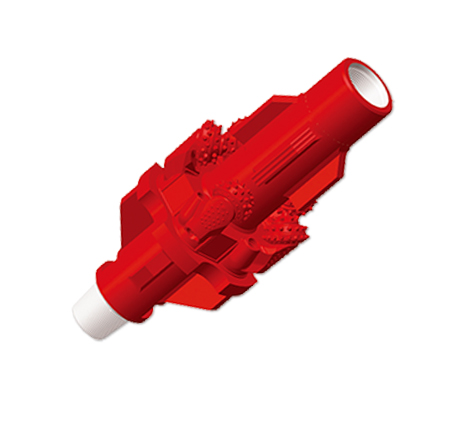
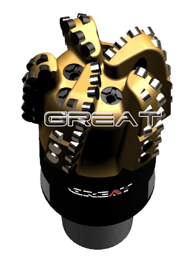
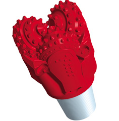
A practical bit program matches each design to its interval, expected formation, hole size, directional objectives, and drilling system. PDC bits use fixed cutters that shear or scrape formation rock. Tricone and other roller-cone bits use rotating cones and teeth or tungsten carbide inserts to break rock through crushing and impact. Neither category is universally superior: the preferred option depends on formation response, operating conditions, and the required drilling behavior.
| Well section | Selection questions | Practical bit-program considerations |
|---|
| Surface | What formations, hole size, and circulation limits are expected? | Prioritize a design and hydraulic arrangement suited to the interval and available rig capacity. Account for hole cleaning and the need to protect the planned wellbore geometry. |
| Intermediate | Are formations hard, abrasive, fractured, interbedded, or prone to balling? | Compare PDC and roller-cone options against offset performance and failure modes. Consider durability, stability, and the ability to maintain effective cleaning. |
| Curve | What directional response and bottomhole assembly behavior are required? | Assess bit steerability and stability in the planned assembly. Review torque, vibration, and the formation transitions expected through the build section. |
| Lateral | How long is the interval, and what are the torque, drag, and gauge-wear risks? | Evaluate durability and gauge protection alongside ROP. Confirm hydraulic performance and hole-cleaning requirements for the trajectory and fluid system. |
The table is a planning framework, not a fixed recipe. Final choices require formation data and the actual hole program. Confirm nominal hole and bit diameters against the approved casing and drilling program; standard size series and bit-size terminology are summarized in the drill bit sizes reference. Do not confuse a bit’s nominal diameter with casing size, pilot-hole diameter, or the final diameter of a later enlarged hole.
For each section, compare offset wells using more than ROP. Review footage drilled, bit hours, dull condition, vibration and torque trends, trips, and the reason for pulling the bit. Where available, evaluate cost per foot using consistent assumptions for bit cost, rig time, and associated operations. A faster bit may not be the lower-cost choice if it wears early or creates additional operational risk.
Gauge Protection and Diamond Reinforcement in Extended-Reach Drilling (ERD)
In extended-reach wells, long contact intervals and directional loading can increase the importance of gauge condition. Wear that reduces effective bit diameter can affect the drilled hole and may complicate subsequent operations. Lateral sections also bring torque and drag, cuttings transport, and vibration considerations. Gauge protection is therefore part of the interval design, not a cosmetic feature.
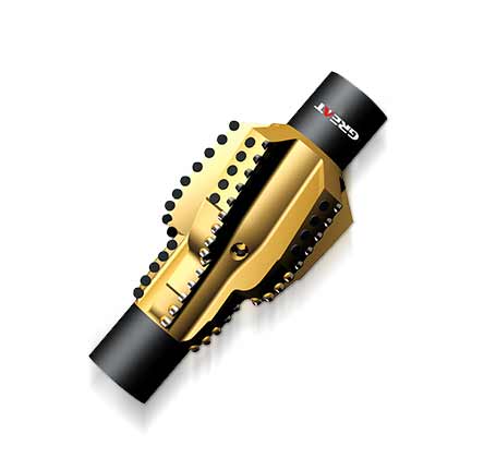
On PDC bits, gauge pads and wear-resistant features help resist abrasion at the bit’s outer diameter. Diamond reinforcement may be used in some designs to improve wear resistance in demanding service. Its value depends on the formation and the bit’s construction; it does not eliminate gauge wear or compensate for poor hole cleaning, excessive vibration, or unsuitable operating parameters. For roller-cone bits, review the gauge-protection features and bearing and cutting-structure suitability for the application.
Choose gauge protection with the formation’s abrasiveness, expected interval length, trajectory, and hole-size requirements in mind. A design intended to resist wear must still be compatible with directional objectives and the required drilling response. Discuss the expected wear mechanism with the bit supplier and specify what should be recorded during inspection, including gauge condition and the distribution of wear across the cutting structure.
For ERD, bit selection cannot solve hole cleaning on its own. Coordinate the bit’s hydraulic design with the planned flow rate, mud properties, annular geometry, and circulation strategy. Monitor drilling indicators and cuttings returns where available. If torque or drag trends worsen, assess hole condition and cleaning alongside the bit and assembly rather than attributing the change to the cutting structure alone.
Deep Well Bit Program Planning and Technical Review Checklist
Use the following checklist before approving a deep-well or HPHT bit program. Record assumptions and unresolved operating constraints so the operator, drilling contractor, and manufacturer are working from the same specification.
Well and interval definition: Confirm section boundaries, nominal hole diameter, trajectory, planned casing points, expected formation sequence, and whether the interval includes hard, abrasive, fractured, interbedded, or balling-prone rock.
Pressure and temperature envelope: Document project-defined HPHT conditions, expected downhole environment, pressure limits, and the ratings required for the bit and associated equipment. Verify limits with the manufacturer.
Bit type and cutting structure: Compare fixed-cutter PDC and roller-cone options against formation behavior, offset performance, durability requirements, and the consequences of vibration or impact.
Mechanical operating plan: Confirm planned WOB, RPM, torque constraints, bottomhole assembly, directional objectives, and monitoring methods. Keep operating parameters within applicable equipment and manufacturer guidance.
Mud and hydraulics: Provide the expected fluid density and rheology data, flow-rate range, pump limits, pressure-loss and ECD constraints, nozzle configuration, and TFA assumptions. Check that the model represents the intended mud system.
Cleaning and balling risk: Assess formation and fluid factors that may promote sticking or packing. Define how drilling response, cuttings, and bit condition will be evaluated.
ERD wear and stability: Review lateral length, gauge requirements, expected abrasiveness, torque and drag concerns, and plans for tracking vibration, hole cleaning, and gauge wear.
Connections and fit: Verify the required bit diameter, connection, rig and drillstring compatibility, and any assembly or clearance requirements. Confirm specifications from the approved program rather than relying on a generic product description.
Performance evaluation: Agree on the field data to capture, including ROP, footage, operating hours, WOB, RPM, torque, pressure behavior, dull condition, and reason for pulling the bit. Use consistent assumptions when comparing cost per foot.
Procurement and technical review: Confirm the final drawing or specification, configuration, delivery requirements, inspection documentation, and communication process for changes to the well plan.
A useful bit-program review ends with a clear link between the formation prognosis, the proposed bit design, modeled hydraulics, operating limits, and the evidence that will be collected after the run. When that link is missing, it becomes difficult to determine whether a result came from the bit, the formation, fluid performance, or operating practice.
Work With a Manufacturer on the Well-Specific Specification
GREAT, the brand of Cangzhou Great Drill Bits Co., Ltd., was founded in 2010 and operates an approximately 86,000 m² manufacturing facility. Its product range includes PDC and tricone bits and other drilling tools in multiple sizes and configurations. Manufacturing capabilities described by the company include CNC and five-axis machining, diamond processing, product design, and engineering development. These capabilities support product manufacturing and customization; the correct design still depends on the well data and agreed operating requirements.
For petroleum applications, share the hole section, target and offset formation information, mud properties, planned hydraulics, trajectory, rig and connection details, operating parameters, and bit-run history when requesting a recommendation. Review GREAT drilling tools for petroleum applications, or contact the team to discuss a project-specific oilfield drill bit specification.
 English
 français
 Deutsch
 Español
 italiano
 русский
 português
 العربية
 tiếng việt
 ไทย
 Nederland