An IADC code helps identify a roller cone bit’s cutting structure, intended formation range, and bearing or gauge design. Read its first three digits as a classification, then check any optional fourth-character feature code. Use the code to screen candidates—not as a substitute for formation data, operating conditions, and the supplier’s complete specification.
This guide explains the roller cone bit numbering system for procurement teams, rig superintendents, toolpushers, and drilling supply distributors. It covers the IADC code chart, the difference between steel tooth and tungsten carbide insert (TCI) series, approximate formation-strength bands, and information to request in a quotation.
What Is the IADC Code System for Roller Cone Drill Bits?
The International Association of Drilling Contractors (IADC) classification system provides a shared way to describe roller cone drill bits. Its main classification consists of three digits. Some bit descriptions add a fourth letter for a special design or application feature. In everyday purchasing language, the system is often called a four-character code, but a letter is not necessarily present.
The code is useful for comparing the general design intent of tricone bits from different suppliers. It does not identify every product detail. Two bits with the same IADC classification can differ in diameter, connection, nozzle arrangement, materials, seal design, cutting structure geometry, and manufacturer-specific features. Confirm those details separately on the technical data sheet.
In practical terms, the first digit identifies the broad cutting-structure and formation series. The second digit narrows the formation category. The third digit describes the bearing and gauge-protection arrangement. An optional letter identifies an additional design feature. The classification applies to roller cone bits; it should not be used to classify fixed-cutter PDC bits.
Decoding the First Three Digits: Series, Type, and Bearing/Gauge Design
Read the numeric code from left to right. For example, in a 537 bit, 5 indicates a TCI series intended for medium-soft formations, 3 indicates a harder subtype within that series, and 7 identifies a sealed journal bearing design with gauge protection. The code describes a general design class; the supplier’s data sheet must confirm the actual bit construction.
First digit: cutting structure and broad formation series
The first digit separates milled-tooth series from TCI series and groups them by intended formation range. Series 1–3 are milled-tooth, or steel-tooth, bits. Series 4–8 are TCI bits. Within each group, higher series generally indicate harder formation applications. This is a selection convention, not a guarantee that a bit will perform in every rock described by that label.
| First digit | Cutting structure | General formation class |
|---|
| 1 | Milled tooth | Soft |
| 2 | Milled tooth | Medium |
| 3 | Milled tooth | Hard |
| 4 | TCI | Soft |
| 5 | TCI | Medium-soft |
| 6 | TCI | Medium-hard |
| 7 | TCI | Hard |
| 8 | TCI | Very hard |
Second digit: formation subtype within the series
The second digit usually ranges from 1 to 4. It subdivides the first-digit series into formation subcategories, generally moving from softer to harder as the number increases. Treat it as a relative classification within that series. It is not a direct compressive-strength value and does not specify a single rock type.
Third digit: bearing and gauge-protection design
The third digit identifies a bearing and gauge-protection class. The following is a commonly used reading of the main codes. Confirm the supplier’s terminology and construction, especially when comparing older designs or specialized products.
| Third digit | Common classification description | Purchasing check |
|---|
| 1 | Standard open roller bearing | Confirm bearing arrangement and lubrication details. |
| 2 | Air-cooled roller bearing | Confirm the bit is designed for the intended air or fluid service. |
| 3 | Open roller bearing with gauge protection | Check gauge-row insert or tooth protection details. |
| 4 | Sealed roller bearing | Confirm seal and lubrication system in the data sheet. |
| 5 | Sealed roller bearing with gauge protection | Check both seal construction and gauge protection. |
| 6 | Sealed journal bearing | Confirm bearing and seal specification for the operating conditions. |
| 7 | Sealed journal bearing with gauge protection | Confirm the gauge-protection design and bit application. |
| 8 | Other or specialized bearing arrangement | Request a precise description; do not infer the design from the digit alone. |
For example, 111 is a soft-formation milled-tooth classification with the first subtype and a standard open roller bearing class. A 537 is a medium-soft TCI classification with the third subtype and a sealed journal bearing with gauge protection. Their differences concern cutting structure, formation intent, and bearing class—not simply bit quality. An IADC 517 tricone bit has the same broad series and bearing/gauge class as 537, but its second digit places it in a softer subtype within series 5.
Decoding the Fourth Letter: Special Application and Cutting Features
A fourth character, when present, is a letter appended to the three-digit classification. It indicates an additional feature, such as a specialized application, nozzle arrangement, or cutting-structure detail. The letter does not replace the numeric classification, and it should not be assumed to have identical wording across every supplier’s catalog.
Commonly encountered supplementary letters include A for air drilling, B for a special bearing or seal feature, C for a center jet, D for deviation control, E for extended jets, G for extra gauge protection, H for horizontal applications, and J for jet deflection. Other commonly listed codes include L for lug pads, M for motor applications, S for standard steel-tooth design, W for an enhanced cutting structure, and X, Y, or Z for particular insert shapes or other insert designs.
Use these descriptions as a decoding aid, not as a substitute for the manufacturer’s legend. If a quotation lists a letter that is unfamiliar or does not explain the feature, ask the supplier to define it in writing. Confirm that the feature is appropriate for the planned drilling fluid, drilling method, hole direction, and bit operating conditions.
Steel Tooth (Series 1–3) vs TCI (Series 4–8) IADC Formations Compared
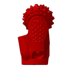
Milled-tooth bits use steel teeth formed on the cones. Their tooth geometry engages the formation through scraping, gouging, and, depending on the rock, crushing. TCI bits use tungsten carbide inserts pressed into the cones. Insert shape, spacing, and exposure affect how the bit engages the rock. Both types rotate on the bottom of the hole, and the cones break formation as they roll under applied weight and rotation.
| Selection factor | Steel-tooth series 1–3 | TCI series 4–8 |
|---|
| Typical code range | 1xx–3xx | 4xx–8xx |
| Typical formation intent | Soft through hard, depending on series and subtype | Soft through very hard, depending on series and subtype |
| Cutting elements | Formed steel teeth | Tungsten carbide inserts |
| Selection emphasis | Tooth shape, exposure, and wear suitability for the formation | Insert shape, placement, and impact or abrasion demands |
| Key limitation | Tooth wear can limit use in abrasive formations | Insert selection and cone design must suit rock strength and fracture behavior |
The distinction is not simply “steel for soft rock, carbide for hard rock.” A soft TCI series exists, and hard milled-tooth classifications exist. Actual selection should account for compressive strength, abrasiveness, interbedding, fractures, expected impact, hole conditions, and the rig’s achievable weight, rotary speed, and circulation. A code narrows the search; drilling history and formation information help determine whether the candidate is appropriate.
As a practical comparison, an IADC 111 vs 537 decision is a choice between a soft-series milled-tooth bit with an open roller-bearing class and a medium-soft TCI bit with a sealed journal-bearing and gauge-protection class. The 537 is not automatically the better choice in every well. A soft, sticky formation may favor a different cutting structure and hydraulic setup than an abrasive or interbedded interval, even when a broad formation label appears similar.
For product options and tricone bit configurations, see GREAT tricone bits. Compare the IADC code alongside diameter, connection, cutting structure, bearing system, and operating recommendations.
IADC Quick Selection Matrix by Formation Hardness and Rock Compressive Strength
The IADC system does not prescribe universal unconfined compressive strength (UCS) limits for each code. The table below provides broad screening bands only. UCS values and terms such as soft or hard vary with the rock type, test method, confinement, porosity, cementation, and local drilling practice. Do not use these bands as an IADC rule or as a stand-alone bit specification.
| Indicative UCS screening band | Broad formation description | Starting IADC series to review | Operational considerations |
|---|
| Below about 5,000 psi (34 MPa) | Very soft to soft | 1xx or 4xx | Review tooth or insert design, cleaning, and risk of balling. |
| About 5,000–10,000 psi (34–69 MPa) | Soft to medium-soft | 1xx–2xx or 4xx–5xx | Consider abrasiveness, interbeds, and the required bearing class. |
| About 10,000–15,000 psi (69–103 MPa) | Medium | 2xx or 5xx–6xx | Compare bit dull records and expected impact or wear. |
| About 15,000–25,000 psi (103–172 MPa) | Hard | 3xx or 6xx–7xx | Assess insert or tooth durability, vibration, and available WOB. |
| Above about 25,000 psi (172 MPa) | Very hard | 7xx–8xx | Confirm the design against abrasiveness, fractures, and actual operating limits. |
These ranges are indicative engineering screening values, not manufacturer-confirmed performance limits. They should not be read as exact boundaries between IADC subtypes. A fractured hard formation can create impact loads unlike those in an intact rock of similar UCS. Abrasive minerals can accelerate wear even when compressive strength is moderate. In layered formations, a bit must also tolerate changes in cutting response across beds.
Before final selection, review available offset-well records, lithology, UCS or other rock-strength data, abrasiveness, expected interbeds, hole size, rig capability, mud or air system, and planned WOB and RPM. Use ROP, bit hours, dull condition, and cost per foot from comparable runs to judge whether a candidate classification makes operational sense.
How to Match IADC Codes to Supplier Quotations and Technical Data Sheets
A purchase order that specifies only an IADC code leaves important product and application details open. Use the code as one line in a complete technical request for quotation (RFP). This makes supplier offers easier to compare and reduces the risk of receiving a bit with the right classification but the wrong connection, diameter, or operating configuration.
Well and application: State the application, hole interval, drilling method, and whether the bit will operate on a motor or rotary assembly.
Formation information: Provide lithology, expected hardness or UCS where available, abrasiveness, interbedding, fractures, and any offset-well bit records.
Bit dimensions: Specify required bit diameter and tolerances, along with any gauge or hole-size requirements.
Connection: Identify the required API connection or other confirmed drill-string connection and request confirmation of compatibility.
Classification and design: Give the preferred IADC code or candidate range, then ask the supplier to state the cutting structure, bearing/seal design, gauge protection, and any fourth-letter feature.
Hydraulics: Confirm nozzle configuration, nozzle options, and the circulation conditions required for the planned drilling fluid or air system.
Operating guidance: Request recommended WOB and RPM ranges for the proposed bit and the relevant operating conditions. Treat supplier guidance as application-specific, not a universal limit.
Inspection and documentation: Ask for the product data sheet, drawing or dimensional confirmation, material or quality documents applicable to the order, and packaging and delivery details.
Commercial comparison: Compare price alongside delivery terms, warranty conditions, technical support, and the supplier’s ability to address the stated formation and application.
When evaluating quotations, check that the stated IADC code matches the description. A 517 and 537 share the series and third-digit bearing/gauge class but differ in the second-digit subtype. If a supplier offers an alternative code, request the reason for the change and a description of the expected trade-off. Do not accept a code-only substitution without reviewing the technical details.
GREAT, founded in 2010, manufactures tricone bits and other drilling tools at an approximately 86,000 m² facility in Hebei, China. Its product range serves applications including oil and gas, water wells, mining, HDD, foundation drilling, and geothermal drilling. For a project-specific quotation, provide the formation details, required dimensions and connection, drilling method, and available operating data so the proposed classification can be assessed against the job.
Field takeaway: The IADC code is a fast classification tool, not a complete buying specification. Decode the series, subtype, bearing/gauge digit, and optional letter; then verify the physical configuration and match it to the formation, rig, and drilling plan.
 English
 français
 Deutsch
 Español
 italiano
 русский
 português
 العربية
 tiếng việt
 ไทย
 Nederland