A successful solid-rock HDD crossing depends on more than choosing a large reamer. Tool direction, cutter condition, formation variability, drilling-fluid return, and the rig’s capacity to manage torque and axial load all affect whether a bore advances steadily or develops a stuck-string problem. Select the reamer for the ground and operating setup, then confirm that the complete drill string and fluid system can support the planned pass.
This field guide is for HDD superintendents, operators, and estimators planning trenchless rock drilling. It explains push- and pull-type reaming, replaceable TCI cutter blocks, hydraulic flushing, torque management, and pre-run inspection. Actual operating limits and assembly details must come from the reamer, rig, drill-string, and project specifications.
Key Considerations When Reaming Solid Bedrock in Trenchless Crossings
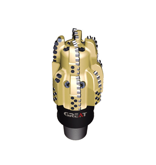
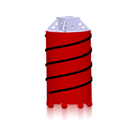
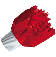
In a rock crossing, the reamer enlarges a pilot bore by breaking and removing formation as it rotates. A horizontal directional drilling rock reamer may use rolling cutters with tungsten carbide inserts (TCIs), fixed cutting elements, or a combination of features, depending on its design. Do not assume that a tool suited to one rock type will perform equally well in another.
Start with the ground model. Record expected rock type, strength variation, abrasiveness, fractures, bedding, weathered zones, and transitions between rock and overburden. Quartz-rich, abrasive formations can wear cutting structures quickly. Fractured or interbedded ground can create uneven loading, vibration, cuttings accumulation, or irregular bore walls. A crossing with changing geology should be planned around the difficult intervals, not just the dominant rock description.
Confirm the bore plan: Define pilot-hole diameter, each reaming stage, final bore diameter, product dimensions, and required clearance. These are different dimensions; do not treat the reamer’s nominal diameter as the product size.
Check the full assembly: Confirm reamer connections, drill-string compatibility, available torque and thrust or pullback capacity, and any required crossover or swivel arrangement.
Plan for cuttings: Estimate how the formation will break and how the drilling fluid will transport solids out of the bore. A cutter can break rock effectively while the operation still struggles if cuttings are not carried away.
Account for the site: Under rivers or other sensitive crossings, monitor returns and fluid pressure according to the project plan. Loss of returns or unexpected pressure can indicate a change in subsurface conditions or fluid pathway.
Choose a rock reamer for HDD applications by considering cutter configuration, diameter, connection, operating direction, formation, and circulation requirements together. For a staged bore, confirm that the proposed sequence suits both the ground and the rig; enlarging too aggressively can increase load on the reamer and drill string.
Pull-Type vs. Push-Type Reaming: Swivel Dynamics and Drill String Tension
In a typical HDD pullback arrangement, the rig pulls the reamer through the pilot bore while the drill string rotates it. The reamer cuts on the return path, and a swivel may connect the reamer assembly to the product pipe so the rotating tooling does not transmit rotation into the product. The swivel’s role and placement depend on the assembly design; it does not eliminate torsional load within the rotating drill string.
A pull-type setup places the drill string primarily in tension during the reaming pass. The crew must still manage combined rotational torque and axial pull, stay within the weakest component’s limits, and monitor for rising load. A pullback rock reamer is not automatically suitable for every pull direction or connection stack: verify that its cutting structure and attachment arrangement are intended for the planned operation.
Push reaming applies axial force from behind the tool. This can be appropriate when the rig, tooling, access, and bore sequence are designed for it, but a drill string under compression is more vulnerable to buckling, particularly in unsupported or curved sections. Push force can also make it harder to distinguish useful cutter engagement from string compression or a developing obstruction.
| Consideration | Pull-type reaming | Push-type reaming |
|---|
| Axial load on string | Primarily tension during the pull | Compression; assess buckling and support |
| Connection and swivel | Confirm reamer, pullback connection, and product swivel arrangement | Confirm connections and tool orientation for the intended push direction |
| Key operational watch | Pull force, torque, returns, and product handling | Push force, torque, string stability, and signs of binding |
| Selection basis | Rig capacity, bore profile, tool design, and pullback plan | Rig and string suitability, access, bore profile, and tool design |
Neither method is universally safer or more efficient. Select the setup using the rig and drill-string ratings, bore geometry, reamer design, and project method statement. Include the swivel, subs, connections, and product handling in the load path review. If the planned operation combines high torque with substantial axial load, confirm acceptable limits with the equipment manufacturers rather than relying on a single rig display.
Replaceable TCI Cutter Blocks: Matching Insert Profiles to Quartzite and Granite
TCI cutters break rock as their cones or cutter assemblies roll and load the formation. Tungsten carbide inserts provide the working contact points. A replaceable cutter block can simplify service when the design allows a worn assembly to be removed and renewed without replacing the complete reamer. The actual service method, fastening system, and replaceable components are tool-specific and should be checked against the manufacturer’s instructions.
Cutter-pocket geometry matters because it positions and supports the cutter assembly under load. Check that pockets are clean, undamaged, and free of cracks, deformation, or looseness. Correct seating and retention help maintain cutter alignment and reduce the risk of a block shifting or being lost. Do not modify a pocket or substitute a block unless the manufacturer approves the part and procedure.
Quartzite and granite are not interchangeable design conditions. Both can be hard and abrasive, but their actual strength, grain structure, fracture behavior, and abrasiveness vary by site. Insert profile, spacing, exposure, and cutter arrangement influence how the tool engages and breaks the rock. More aggressive engagement is not always better: it can increase impact loading or torque in fractured, heterogeneous, or variable ground.
When specifying a TCI cutter rock reamer, provide the formation description and any available geological or drilling records. Ask the supplier to confirm the cutter profile and assembly intended for the expected rock and operating direction. Also confirm whether cutters are replaceable in the field, what parts are considered serviceable, and what inspection or replacement criteria apply. Avoid judging cutter suitability from insert appearance alone.
Hydraulic Flushing and Mud Jet Optimization to Prevent Reamer Caking
Drilling fluid helps cool and clean the cutting structure, carry rock cuttings through the annulus, and support the bore. Hydraulic performance depends on the complete system: pump capacity, fluid properties, drill-string and tool passages, nozzle configuration, annular space, and the formation’s ability to accept or return fluid. A nominal pump rate alone does not prove that the reamer is being cleaned effectively.
Flow distribution is as important as total flow. Jets and passages should direct fluid toward the cutting areas and help move dislodged material away from the tool. A blocked or damaged nozzle, poorly distributed flow, or accumulated debris can leave cutters packed with cuttings. Caking can reduce effective cutting, increase torque, and contribute to poor returns or a stuck assembly.
Before the run, inspect nozzles and fluid passages for blockage, wear, damage, and correct installation.
Confirm the mud program with the drilling-fluid provider and project plan; account for formation, cuttings transport, and bore stability rather than selecting fluid on viscosity alone.
During reaming, track pump pressure and flow alongside torque, axial load, returns, and progress. Interpret changes together instead of treating one reading as a diagnosis.
If returns change or circulation becomes abnormal, follow the project response plan. Do not increase pressure or flow beyond the rated capacity of the rig, tool, connections, or ground-control plan.
There is no universally correct jet size, flow rate, or mud property for every HDD rock crossing. Establish operating targets using the tool’s hydraulic design, pump capability, bore geometry, fluid program, and formation response. Maintain a clear record of baseline readings so the crew can recognize meaningful changes during the pass.
Managing Rotational Torque and Avoiding Stuck Pipe Disasters Under Rivers
High or rapidly changing torque can indicate increased cutter loading, a formation transition, inadequate cuttings removal, mechanical interference, or a developing stuck condition. It is a warning signal, not a standalone diagnosis. Compare torque with axial load, rotation, circulation, returns, and progress. A rise in torque while advancement slows deserves prompt attention under the project’s operating procedure.
Under a river, the crew may have limited access to the bore and must manage inadvertent fluid returns and environmental constraints. Review the crossing plan, fluid-loss response, monitoring responsibilities, and stop-work criteria before drilling. Do not respond to a stalled tool by automatically applying more rotation, pull, or push; added load can exceed component limits or worsen a mechanical problem.
Use the project-approved operating envelope for torque, thrust, pullback, rotation, and circulation.
Trend readings and communicate changes between the rig operator, superintendent, and fluid crew.
Keep connections, drill pipe, reamer, and swivel within their documented ratings; the lowest-rated component governs the assembly.
If the tool stops advancing, assess circulation, returns, load trends, and likely formation conditions before choosing a response.
Follow the site contingency plan for loss of returns, unexpected pressure, suspected stuck pipe, or surface fluid release.
Pullback thrust management means controlling axial force while maintaining the rotation and circulation needed for cutting and cleaning. Smooth, coordinated operation and early recognition of abnormal trends are more useful than reacting to a single peak reading. Establish escalation limits and communication roles before the reamer enters the crossing.
HDD Rock Reamer Pre-Run Inspection and Maintenance Protocol
A documented pre-run inspection catches damage and configuration errors before they become downhole problems. Use the reamer manufacturer’s service instructions and the project’s inspection requirements; the list below is a practical field check, not a substitute for either.
Identify the tool: Confirm the reamer type, intended operating direction, nominal diameter, connection, and compatibility with the planned bore stage.
Inspect the body: Look for cracks, deformation, severe wear, damaged welds where applicable, and evidence of previous overheating or impact.
Check cutters: Inspect inserts and cutter assemblies for missing, chipped, cracked, loose, or excessively worn components. Confirm that replaceable blocks are correctly seated and retained according to instructions.
Examine pockets and retention: Check pocket surfaces and fasteners or locking features for damage, contamination, looseness, or unauthorized repair.
Check rotation components: Where the design includes rolling cutters or bearings, verify condition and movement using the manufacturer’s procedure. Do not assume all assemblies are field-serviceable.
Verify hydraulics: Check nozzles and passages, remove obstructions using an approved method, and confirm the planned fluid path is open.
Inspect connections: Clean and examine threads and shoulders; confirm correct make-up procedure, compatible subs, and connection condition.
Review the load path: Confirm ratings and configuration for drill string, reamer, swivel, pullback connection, and product handling equipment as applicable.
Record condition: Photograph or document wear and any maintenance before deployment, then compare with the post-run inspection.
After the pass, clean the tool and inspect cutters, pockets, body, connections, and fluid outlets before deciding whether it is ready for another run. Record the formation interval, operating observations, and observed wear. That information helps the project team and supplier refine cutter selection and maintenance planning for subsequent stages.
Plan the Reamer Around the Crossing
A dependable HDD rock reamer setup matches cutter design and operating direction to the formation, while keeping torque, axial load, and circulation within verified equipment and project limits. Before ordering or mobilizing, share the bore-stage diameters, geology, rig and connection details, planned push or pull arrangement, and fluid-system constraints with the tool supplier.
GREAT manufactures rock reamers and other drilling tools for HDD and related applications. For a project-specific configuration, review GREAT rock reamer options and provide the crossing requirements for technical discussion.
 English
 français
 Deutsch
 Español
 italiano
 русский
 português
 العربية
 tiếng việt
 ไทย
 Nederland