Drill bit hydraulics nozzle sizing connects pump flow and pressure to the fluid energy available at the bit. Correct nozzle sizing can help clean the cutting structure, carry cuttings away from the bottom of the hole, and support efficient mechanical drilling. The practical task is to balance flow rate, total flow area (TFA), bit pressure drop, jet velocity, hydraulic horsepower per square inch (HSI), and the drilling system’s operating limits.
This guide explains the core calculations and provides a worksheet-style example. The example is illustrative, not a universal operating recommendation. Confirm actual flow limits, pressure losses, nozzle dimensions, and bit requirements for the specific rig, fluid, drill string, and formation.
The Critical Link Between Bit Hydraulics and Rate of Penetration
Mechanical rate of penetration (ROP) depends on how effectively the bit’s cutters or teeth break the formation. Hydraulics do not replace weight on bit (WOB), rotary speed, or a suitable cutting structure. They affect how well the bit can work by moving fluid across the cutting face, cooling the cutters, and removing generated cuttings.
When fluid flow is insufficient or poorly directed, cuttings can remain near the bit instead of entering the annulus. The bit may then regrind cuttings, work against a packed face, or experience reduced cleaning around its cutting elements. In reactive or sticky formations, material can adhere to the bit and contribute to balling. These conditions can reduce effective rock removal and make ROP less consistent.
Increasing flow or changing nozzle area may improve cleaning, but it also changes pressure losses and hydraulic energy distribution. The available pump pressure must cover drill-string and surface losses, downhole tool losses where applicable, annular losses, and the pressure drop across the bit. A nozzle change that raises bit pressure drop can exceed the pump or tool operating limit even if it produces stronger jets.
Hydraulic optimization therefore starts with the whole circulating system, not the bit alone. Review flow rate, mud density and rheology, solids loading, hole size, drill-string dimensions, motor requirements, and the pressure budget. Then choose a TFA that gives useful cleaning while remaining within the operating envelope.
Calculating Total Flow Area (TFA): Sizing Nozzles in 32nds of an Inch
Total flow area is the sum of the open cross-sectional areas of all installed bit nozzles. For round nozzles, calculate each area using its diameter, then add the areas together:
TFA = Σ (π × d² ÷ 4)
Here, d is each nozzle’s inside diameter and TFA is expressed in square inches when diameters are in inches. For a set of identical nozzles, the formula becomes TFA = N × π × d² ÷ 4, where N is the number of nozzles.
Many bit nozzle sizes are specified in 32nds of an inch. Convert the size to inches by dividing the stated number by 32. For example, a 12/32-in nozzle has a diameter of 12 ÷ 32 = 0.375 in. Its area is approximately 0.110 in². Three equal 12/32-in nozzles therefore have a combined TFA of approximately 0.331 in².
For mixed nozzle sizes, calculate each nozzle separately. For example, two 12/32-in nozzles and one 13/32-in nozzle have a combined TFA of approximately 0.351 in². Do not add nozzle diameters to estimate TFA: area changes with the square of diameter.
| Nozzle size | Diameter (in) | Approx. area (in²) |
|---|
| 10/32 | 0.3125 | 0.077 |
| 12/32 | 0.3750 | 0.110 |
| 13/32 | 0.4063 | 0.130 |
| 14/32 | 0.4375 | 0.150 |
The table gives rounded geometric areas for individual circular nozzles. The installed bit TFA is the sum across all open nozzles. Confirm the actual nozzle configuration and dimensions from the bit documentation before using a calculation to set operating parameters.
At a fixed flow rate, reducing TFA increases average flow velocity through the nozzle openings and generally raises bit pressure drop. Increasing TFA generally lowers nozzle velocity and bit pressure drop at the same flow rate. In a real circulating system, flow rate may also change because the pumps and the rest of the system operate against a combined pressure-loss curve.
Jet Impact Force vs Hydraulic Horsepower per Square Inch (HSI): Finding the Sweet Spot
Two useful ways to assess bit hydraulics are jet action at the bottom and the hydraulic power delivered across the bit. They describe related but different aspects of the flow. HSI describes hydraulic horsepower per unit of bit face area; it does not, by itself, show how fluid is distributed across the bit or how effectively the jets remove cuttings.
In oilfield units, hydraulic horsepower across the bit can be estimated as:
Bit hydraulic horsepower (hp) = bit pressure drop (psi) × flow rate (gpm) ÷ 1,714
Then calculate HSI as:
HSI (hp/in²) = bit hydraulic horsepower ÷ bit face area
For a circular bit, face area is π × bit diameter² ÷ 4. State the area convention when comparing HSI values: the calculation above uses the full circular bit face area. HSI comparisons are meaningful only when the flow, pressure-drop, and area definitions are consistent.
Jet velocity is another useful indicator. For flow rate Q in gallons per minute and TFA in square inches, average nozzle velocity is approximately:
Average jet velocity (ft/s) = 0.3208 × Q ÷ TFA
This is an average velocity based on total open area. Actual nozzle discharge is affected by fluid properties, nozzle geometry, and discharge behavior. Jet impact at the formation also depends on nozzle direction, stand-off, bit-face geometry, and how the flow interacts with the bottom-hole environment. A calculated velocity is not a direct measurement of impact force at the rock surface.
A simplified orifice estimate can connect flow and pressure drop. In SI units, an idealized relation is ΔP = ρ/2 × [Q ÷ (CdA)]², where ΔP is pressure drop in pascals, ρ is fluid density in kg/m³, Q is volumetric flow in m³/s, A is total nozzle area in m², and Cd is a discharge coefficient. This estimate assumes equivalent nozzles and simplified flow behavior. Use validated hydraulic software, bit data, or field pressure measurements for design decisions; do not treat an assumed coefficient as a manufacturer-confirmed value.
Higher jet velocity can increase local momentum and help dislodge cuttings, while greater hydraulic power can support flow through the bit and cleaning across the face. But maximizing one metric is not the objective. Excessive pressure drop can consume the pump-pressure budget, and aggressive jetting may increase erosion risk. Too much TFA for the available flow can leave weak jets and poor local cleaning. The practical target is the best cleaning and cooling that the system can sustain without exceeding equipment limits.
Preventing Bit Balling and Secondary Cuttings Grinding at the Well Bottom
Bit balling occurs when sticky formation material accumulates on the bit face or around cutting elements. The risk depends on formation behavior, fluid chemistry and properties, bit design, operating conditions, and the effectiveness of fluid circulation. No single nozzle size prevents balling in every formation.
Hydraulics can help by directing sufficient flow across the face and away from areas where cuttings tend to collect. If the bit repeatedly encounters cuttings that have not cleared the bottom, those particles may be ground again. This secondary grinding uses energy without producing the same net advance as cutting fresh formation. In practice, check whether the symptoms coincide with poor returns, a packed bit face, unstable ROP, or changes in torque and pressure. Interpret these observations with the formation and drilling-fluid behavior; they are not unique proof of a nozzle problem.
Evaluate nozzle position and orientation alongside total area. The same TFA can produce different cleaning patterns when ports are arranged differently. Consider the bit’s cutting structure, face profile, gauge, nozzle locations, and the available flow path. For PDC applications, cutter exposure and blade layout also influence how fluid reaches the cutting face. Review the bit design and intended operating conditions with the manufacturer rather than selecting TFA in isolation.
Bottom-hole cleaning is not the same as annular hole cleaning. Bit jets act locally at the bottom; transport through the annulus also depends on annular velocity, hole and drill-pipe sizes, fluid rheology, inclination, cuttings loading, and flow regime. A strong jet does not guarantee that cuttings will be transported effectively all the way to surface.
When reviewing a bottom-hole cleaning or RFA metric, first confirm exactly how that metric is defined and what flow area it includes. Acronyms and calculation conventions are not always consistent between programs or organizations. Use the same definition when comparing runs, and pair any calculated index with field evidence such as returns, pressure behavior, cuttings condition, and bit inspection.
Nozzle Velocity Limits: Balancing Cavitation Erosion Against Effective Cooling
There is no single nozzle-velocity limit suitable for every bit, fluid, and drilling system. High local velocities can contribute to wear or erosion, particularly where fluid contains abrasive solids. Cavitation is possible when local pressure falls sufficiently for vapor cavities to form and then collapse as pressure recovers. Whether that occurs depends on local pressure, fluid properties, nozzle geometry, and operating conditions; a simple average-velocity calculation cannot confirm cavitation.
At the other end of the trade-off, insufficient flow may limit cutter cooling and reduce the fluid available to clear cuttings from the bit face. Evaluate cooling and cleaning together with pressure drop, not as separate goals. Check for nozzle or port erosion during inspections, compare observed pressure with the hydraulic model, and investigate unexplained changes in flow or pressure. Use bit-specific operating guidance and the limits of the rig, pumps, drill string, and downhole tools.
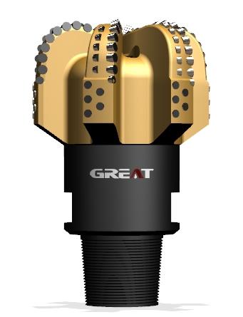
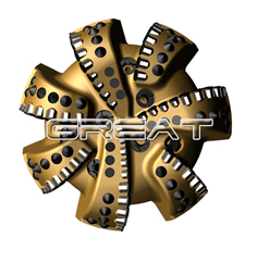
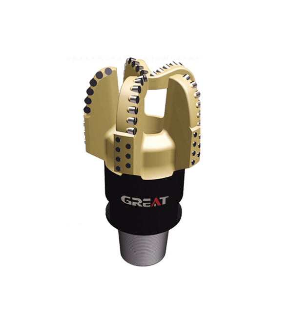
For a PDC bit, nozzle layout and flow distribution should suit the cutting structure and the application. GREAT manufactures PDC drill bits in multiple configurations; share formation, hole size, flow-rate range, fluid details, and pressure constraints when discussing a project-specific bit. See GREAT PDC drill bits.
Step-by-Step Drill Bit Nozzle Selection and TFA Calculation Worksheet
Use this sequence to organize a drill bit nozzle sizing review. The numerical example is a simplified calculation, not a recommended operating point.
Record the operating inputs. Note planned flow rate, mud density and properties, bit diameter, nozzle count and sizes, pump-pressure limit, expected drill-string and annular losses, and any motor or tool pressure requirements.
Calculate TFA. Convert each nozzle size from 32nds to inches, calculate πd²/4 for each opening, and sum the individual areas.
Estimate average jet velocity. Use 0.3208 × flow rate in gpm ÷ TFA in in². Treat this as a comparative estimate, not a direct measurement at the formation.
Estimate bit pressure drop. Use an appropriate hydraulic model with fluid properties and nozzle discharge behavior, or use validated field data. Keep bit pressure drop separate from other system losses.
Calculate bit hydraulic horsepower and HSI. Apply ΔP × Q ÷ 1,714 in oilfield units, then divide by the stated bit-face area.
Check the system and the drilling response. Confirm pump, drill-string, motor, and bit limits. After operating, compare actual pressure and returns with expectations, then assess cleaning, ROP, vibration, and signs of wear or balling.
Worked example with illustrative inputs
Assume a bit has three 12/32-in nozzles, the flow rate is 500 gpm, the bit diameter is 8.5 in, and mud density is 1,200 kg/m³. These values are selected to demonstrate the arithmetic, not to prescribe a field setup.
Nozzle diameter: 12 ÷ 32 = 0.375 in.
Area per nozzle: π × 0.375² ÷ 4 ≈ 0.110 in².
Total flow area: 3 × 0.110 ≈ 0.331 in².
Average jet velocity: 0.3208 × 500 ÷ 0.331 ≈ 485 ft/s.
Bit face area: π × 8.5² ÷ 4 ≈ 56.7 in².
To illustrate the pressure and HSI calculations, suppose a simplified orifice estimate using an assumed discharge coefficient of 0.95 gives a bit pressure drop of approximately 1,880 psi. This is an assumed model output for the example, not a GREAT specification or a confirmed field measurement.
Bit hydraulic horsepower: 1,880 × 500 ÷ 1,714 ≈ 548 hp.
HSI: 548 ÷ 56.7 ≈ 9.7 hp/in², using the full circular bit face area.
The example shows why nozzle choice must be checked against the complete pressure budget. A calculated bit pressure drop of 1,880 psi would need to fit within the pressure available after accounting for all other losses and tool requirements. If it does not, revise the flow, TFA, or operating plan and recalculate. Do not infer a suitable operating point from HSI or jet velocity alone.
For a field worksheet, preserve the assumptions beside every result: nozzle sizes and count, actual flow rate, fluid density, pressure-loss method, discharge-coefficient basis, bit diameter, and bit-face area convention. Compare calculated values with measured standpipe pressure and observed drilling behavior. That record makes it easier to distinguish a nozzle-sizing issue from changes in fluid properties, system losses, formation response, or bit condition.
For a project-specific review, provide the expected formation, bit size and type, flow range, mud information, available pressure, and downhole tool constraints. GREAT’s engineering team can use those inputs to discuss a suitable bit configuration and hydraulic design; final nozzle selection should be verified against the actual drilling program and equipment limits.
 English
 français
 Deutsch
 Español
 italiano
 русский
 português
 العربية
 tiếng việt
 ไทย
 Nederland