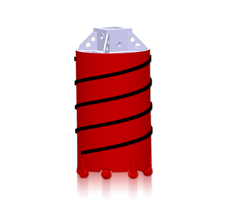
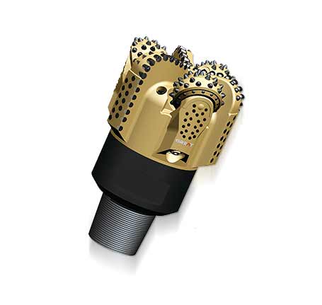
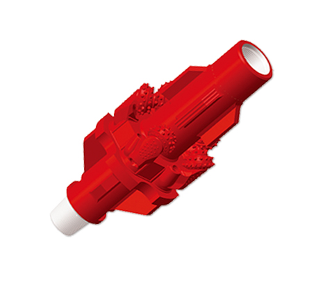
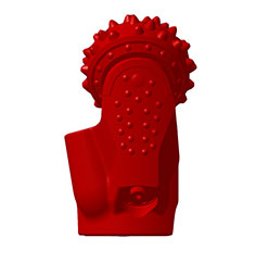
A bi center drill bit uses an eccentric cutting structure to pass through a restrictive casing opening and drill a larger hole below it. The key design check is whether the tool’s pass-through envelope fits the actual casing restriction while its cutting structure produces the required hole diameter. That geometry can help address tight wellbore clearance, but it does not by itself guarantee directional stability, casing clearance, or cementing performance.
For well designers, the decision depends on the complete downhole assembly, casing and shoe dimensions, formation, trajectory, and operating limits. This guide explains the geometry and the engineering checks to complete before selecting a bicenter PDC bit for hole enlargement while drilling.
What Is a Bi-Center Drill Bit and Why Is It Used?
A bi-center bit is a fixed-cutter drilling tool with an eccentric cutting profile. Its run-in profile is smaller than the hole it can drill: the tool passes through a restricted opening, then its offset cutting structure enlarges the bore as the assembly advances below that restriction. Depending on the design, the assembly may combine a pilot section with an eccentric reaming section.
The practical purpose is to create a larger hole below an existing casing restriction without first running a separate, full-diameter tool through the entire casing string. This can be useful when a planned hole size, casing program, or wellbore geometry leaves insufficient space for a conventional concentric bit or reamer to pass.
A bi-center tool is not automatically a casing drilling bit. In casing drilling, the casing itself is part of the drilling assembly. A bi-center bit may instead be run through installed casing to drill or enlarge the formation below the shoe. Confirm the planned operating method and shoe compatibility with the tool designer.
Bi-center designs are considered when engineers need to manage a restrictive internal passage and achieve a larger drilled diameter below it. The design must suit the formation and drilling system. Fixed cutters can shear or scrape formation, but cutter layout, hydraulics, formation abrasiveness, compressive strength, and vibration exposure all affect performance and wear.
Review GREAT’s bi-center bit as a starting point for discussing a project-specific configuration. Tool suitability still needs to be checked against the well design and operating conditions.
Understanding Pass-Through Diameter vs Drill Hole Diameter
The pass-through diameter is the limiting run-in envelope that must clear the casing restriction. The drill hole diameter is the diameter the cutting structure is designed to produce below the restriction. These are different design values. A tool can have a pass-through envelope smaller than its intended drilled diameter because the cutting structure is eccentric.
Do not compare only the nominal pilot-bit diameter with the casing inside diameter. Check the maximum outside envelope of the complete assembly, including the bit, reamer features, stabilizers, connections, and any other component that must pass through the restriction. Also account for the actual minimum opening, not just the casing’s nominal size.
In practice, the limiting opening may be affected by the casing drift diameter, connections, internal profiles, wear, deformation, debris, or other downhole restrictions. The casing drift dimension and tool envelope should be verified from the applicable equipment records and measurements. A nominal casing size alone is not enough to establish clearance.
Likewise, the intended hole diameter must be confirmed from the tool design rather than inferred from its run-in profile. Ask the manufacturer to state the specified pass-through envelope, intended drilled diameter, connection details, and any orientation or operating constraints. Confirm whether those dimensions refer to the bit alone or to the full assembly.
For casing-clearance calculations, distinguish casing outside diameter from casing inside diameter. In a concentric, circular geometry, nominal radial clearance is half the difference between the drilled-hole diameter and casing outside diameter. Actual local clearance can be lower where the casing is eccentric, the hole is irregular, or the assembly and wellbore are not centered. Therefore, a nominal diameter calculation is a screening check, not proof of uniform clearance.
Mitigating Casing Restrictions and Expanding Annular Cementing Clearance
A bi-center bit can address a geometric problem: the tool must pass through a smaller opening than the hole required below it. By enlarging the hole while drilling ahead, the tool may create more space around a subsequent casing string than a smaller, concentric hole would provide. Whether that space is sufficient depends on the drilled diameter, casing outside diameter, hole condition, centralization, and the cementing design.
More nominal annular area does not guarantee better cement placement. Eccentricity, ledges, washouts, cuttings beds, mud properties, casing standoff, and circulation conditions can affect displacement and cement distribution. A larger hole also changes the annular volume that must be planned for. The cementing team should use the expected hole geometry and operational uncertainties when evaluating volumes and placement.
Before selecting a tool, compare at least three dimensions: the minimum casing restriction, the tool’s maximum pass-through envelope, and the required drilled-hole diameter. Then check the casing shoe and any shoe-track or float equipment that the assembly may encounter. Confirm which components are intended to be drilled, passed, or left undisturbed. Do not assume a bi-center cutter is suitable for cutting casing or every shoe material.
For a tight wellbore clearance problem, the design review should also consider the next casing string’s outside diameter, connection geometry, expected hole tolerance, and running clearance. If the plan relies on a minimum clearance, evaluate the consequences of a smaller-than-target hole or local ledges. A nominal target diameter cannot describe every point around an eccentric, irregular bore.
Bi-center geometry can be a useful option where the casing restriction prevents passage of a conventional full-gauge tool. It is not a substitute for checking casing integrity, drift, shoe condition, hydraulics, cuttings transport, or the cementing program.
Directional Control and Vibration Management with Eccentric Cutting Structures
An eccentric cutting structure does not load the formation symmetrically in the same way as a concentric bit. The resulting side forces and contact pattern can influence toolface response, lateral vibration, borehole trajectory, and the behavior of a directional assembly. The effect depends on the bit design, formation, bottom-hole assembly, and drilling mode; it should be assessed for the specific well rather than assumed from the tool category alone.
Formation changes matter. Interbedded or fractured intervals can produce uneven cutter engagement. Hard, abrasive rock can raise cutter wear and torque demand, while softer or less competent formations may respond differently to the eccentric cutting action. Changes in formation strength can also alter the balance of forces and make drilling response less predictable.
For directional wells, review the bit with the planned motor or rotary steerable system, stabilizer arrangement, bend setting where applicable, and required trajectory. Confirm that the assembly can deliver the steering response and toolface control the well plan requires. A tool that fits through casing may still be unsuitable for the planned directional section.
Vibration management starts with matching the cutting structure and operating envelope to the formation. Monitor torque, vibration indicators, weight on bit (WOB), rotary speed (RPM), rate of penetration (ROP), and hydraulic behavior. Unstable torque, repeated stalls, excessive vibration, or deteriorating cuttings removal are reasons to review drilling parameters and the assembly response. No single indicator should be interpreted without the operating context.
Hydraulic design is also important. Nozzle configuration and available flow should support cutter cleaning and cuttings transport without exceeding the pressure limits of the drilling system. Confirm that the planned flow path, mud properties, and pump capacity are compatible with the bit and assembly. Poor cleaning can reduce cutting efficiency and increase the risk of recutting cuttings.
Optimal RPM and WOB Parameters When Drilling Through Casing Shoes
There is no universal RPM or WOB setting for a bi-center bit. Suitable values depend on the specific bit design, formation, rig or motor limits, hydraulics, bottom-hole assembly, and the transition across the casing shoe. Use the manufacturer’s operating guidance and the limits of the complete drilling system rather than applying a generic range.
Plan the shoe transition deliberately. Confirm the expected shoe and shoe-track materials, the point at which the bit enters formation, and any components that could affect the cutters. Follow the approved procedure for the specific shoe and assembly. Avoid abrupt changes in WOB or RPM that could create a sudden change in engagement; use monitored, controlled parameter adjustments appropriate to the drilling program.
During drilling, interpret WOB and RPM alongside torque, ROP, vibration, standpipe pressure, and returns. A rise in torque or vibration may indicate changing formation response, cutter engagement, or a mechanical issue; it does not identify a single cause by itself. If ROP falls while torque or vibration changes, review the formation, hydraulics, and assembly before increasing WOB.
For a motor-driven assembly, account for the motor’s operating limits and the interaction between motor speed, torque, bit loading, and flow. For rotary drilling, confirm that surface RPM and torque capacity are appropriate. In both cases, the goal is stable cutting and effective hole cleaning within the approved operating envelope, not simply the highest attainable ROP.
Bi-Center Bit Feasibility and Well Design Checklist
Use this checklist during casing, bit, and bottom-hole assembly reviews. Resolve any dimensional or operating uncertainty with the tool manufacturer and the responsible well-design disciplines before mobilization.
Define the objective: State the target drilled diameter, interval to be enlarged, and reason a conventional concentric tool cannot meet the passage requirement.
Verify the restriction: Confirm the minimum available casing opening from applicable drift data, connection dimensions, internal profiles, and known downhole restrictions.
Confirm the full pass-through envelope: Obtain the maximum run-in dimensions for the complete assembly, not only the pilot bit or nominal body size. Include all components that must pass the restriction.
Confirm the drilled diameter: Obtain the tool’s intended hole diameter and understand the design assumptions behind it. Do not treat pass-through diameter and drilled-hole diameter as interchangeable.
Review shoe compatibility: Identify the shoe, shoe-track, and float equipment materials and clarify which components the assembly is expected to drill through or avoid.
Check casing and cementing geometry: Compare drilled-hole diameter with casing outside diameter, assess expected eccentricity and hole irregularity, and coordinate annular-volume and placement assumptions with the cementing plan.
Assess formation and trajectory: Provide formation descriptions, expected strength and abrasiveness, interbedded or fractured intervals, inclination, and directional-control requirements.
Check assembly compatibility: Verify connections, motor or rotary system, stabilizers, steering equipment, rig torque capacity, and any component-specific operating limits.
Review hydraulics and cuttings transport: Confirm flow, pressure limits, mud properties, nozzle design, and hole-cleaning requirements for the planned hole size and operating mode.
Agree on operating and monitoring plans: Establish manufacturer-supported parameter guidance and identify the torque, vibration, pressure, and ROP trends that will trigger a review.
Plan contingencies: Define responses to restricted passage, unexpected shoe conditions, poor hole cleaning, unstable drilling, or a hole diameter that does not meet the casing plan.
A bi-center bit is feasible when its verified pass-through envelope clears the actual restriction, its cutting geometry produces the required hole, and the assembly can drill the interval within the well’s mechanical and hydraulic limits. The critical design task is to verify those conditions together—not to select the tool from nominal diameters alone.
GREAT manufactures drilling tools including bi-center bits and other specialized products. Its stated manufacturing resources include an approximately 86,000 m² facility with CNC and five-axis machining capabilities. For a project review, provide the casing and shoe details, target hole diameter, formation information, trajectory, and planned drilling system so the tool configuration can be assessed against the application.
 English
 français
 Deutsch
 Español
 italiano
 русский
 português
 العربية
 tiếng việt
 ไทย
 Nederland